From my highschool’s maker club I got an old ATI Radeon HD3450 GPU from broken school computers that were being salvaged for their power supplies. I wanted to learn how the graphics card worked electrically, and try modifying it to understand the power delivery circuit worked. Sadly I didn’t get a chance to try modifying the circuit at the time because this HD3450 only has an S-Video port and a DMS-59 port to output video, neither of which I have a cable for. Looking into the DMS-59 standard I found that it was a way for companies to include 2 VGA ports in one smaller port for small GPUs, and that electronically it had two VGA cables inside it. I thought this would be a perfect opportunity for me to learn how to design a PCB, so I could get this card working and experiment with it.
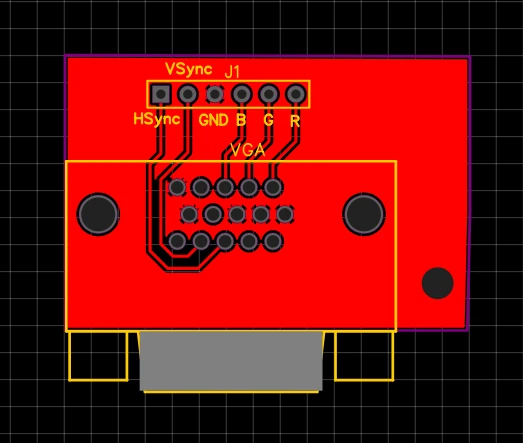
My friend Varun recommended EasyEDA for PCB development because of its ease of use and integration with JLC PCB and LCSC, so I used it to start working on my board. It ended up being a really simple design, as I essentially just made a breakout board that I could mount on the hole previously used for the GPU’s mounting bracket. My plan is to screw the VGA breakout PCB onto this hole and solder wires to the corresponding pins on the back of the DMS-59 port, and then use female pin headers on the other end of the wire to plug into my PCB. Due to long shipping times from China, I have not received this board and tested it yet.
The breakout board for a VGA connector
Having successfully created my first PCB I thought I may as well make another for a future project, since they were going to take around a month to arrive anyways. I have a future project in mind where I would like to use a low pin count microcontroller and program it in bare-metal C, so I decided to make a development board for the ATTiny 414. The ATTiny 414 was perfect for this project because it was a small, cheap, low power microcontroller with an Analog Comparator, SPI hardware, and it can be programmed with a simple UDPI programmer. The main focus of this project was to get this chip on a development board so I could have access to all the pins, and program and power it with a USB cable.
When looking for a USB to UDPI converter I stumbled across a really interesting project called pyudpi which looked like the best solution. It uses a python utility to drive a USB to UART converter IC in such a way that it generates a UDPI signal, only adding an additional 1k ohm resistor to the circuitry. This is what allowed me to add the programmer into the board instead of relying on a bulky, expensive external UDPI programmer.
The development board for an ATTiny 414
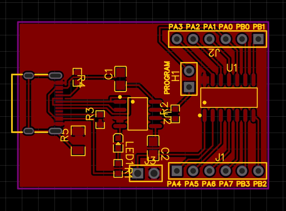
I followed the recommendations on the datasheet for the CH340N USB to UART chip I used, and added decoupling capacitors as it recommended. I calculated I needed a 360 ohm resistor for the blue LED I was using based on its data sheet, and an equation I found for calculating the required resistor value for an LED: (circuit voltage - LED voltage) / LED amperage. Finally I found a guide for how to connect the USB C port I had used to configure it for USB 2.0 mode for my project, and included a header to connect pin PA0 to the programmer only if a jumper was placed over a pin header. Routing the PCB was difficult due to the closely packed pins in the USB C header, but with a bit of creative routing I was able to make this PCB single sided.